Description
Properties of State Transition Matrices
General Properties
Each arrow corresponds to the proportion of a node that is being transferred to another node (each entry will be ≤1).
The only arrows that are present are the arrows that are drawn. A nonexistent arrow implies that the flow between the nodes is 0. Do not add arrows to make the total flow leaving the node sum to one.
A row corresponds to the inflow to a node.
A column corresponds to the outflow of the node.
If any of the rows are linearly dependent, the transition matrix is not invertible!
However, when you apply a dependent transition matrix to a vector, the two corresponding entries to the dependent rows in the vector with be related (i.e. if row1=2⋅row2, then the resulting vector will have entry1=2⋅entry2).
Column Properties
If the entries in each columns sum to one, this means that whatever is being transferred is conserved. This means nothing is lost and gained as the matrix is applied!
If the entries in each columns sum to less than one, this means that the system is gradually losing whatever is being transferred.
If the entries in each columns sum to more than one, this means that the system is gradually gaining whatever is being transferred.
Procedure
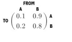
Label each column with a node. Label each row with a node. We can view the columns as where the arrow is FROM and the rows as where the arrow is going TO. For example, let's consider a system with two nodes, A and B.

The value corresponding to the entry at (A, A) is the arrow that goes from node A to node A. The entry at (B, A) is the arrow that goes from node B and goes to node A.
Example
Graph
Incidence Matrix

$$\begin{bmatrix}
e{AA} & e{BA} &e{CA} \ e{AB} &e{BB} & e{CB} \ e{AC} &e{BC} & e_{CC} \ \end{bmatrix}
Because the sum of each column is equal to one, the system is conservative.
Notation for Incidence Matrices
In edge-node incidence matrices, columns represent nodes while edges represent rows. Flow into a node in represented by −1 while flows out of a node are represented by +1 in the respective entry in the incidence matrix. This convention is very important when it comes to circuits so be sure use this convention!
Example
Graph
Incidence Matrix
$$\begin{bmatrix}
1 & -1 & 0 & 0\ 0 & 1 & -1 & 0\ -1 &0 & 1 & 0\ 1 & 0 & 0 & -1 \end{bmatrix}
Multiplying the incidence matrix by a vector containing all the nodes: 10−11−11000−110000−1abcd=a−bb−cc−aa−d As you see, we will get the potential difference across each edge (Entry 1 corresponds to flow 1 etc).
Let's do the same thing again but with the transpose of the matrix times a vector containing the flows.
Let's denote each edge as i. In this example, there are four flows, i1,i2,i3, and i4. 1−10001−10−1010100−1i1i2i3i4=i1−i3+i4i2−i1i3−i2−i4 As you see, each entry in the resulting vector shows the flows in and out of each node. We will go more into depth about what exactly this means in the future lectures about circuits!
Last updated
Was this helpful?